Detailed Instructions
1. Open the ACCS.net Administration Site with a web browser at http://admin.accs.net.
2. Log in to the Administration site using an appropriate Username (UserID) and Password (Pass) (Figure 1).
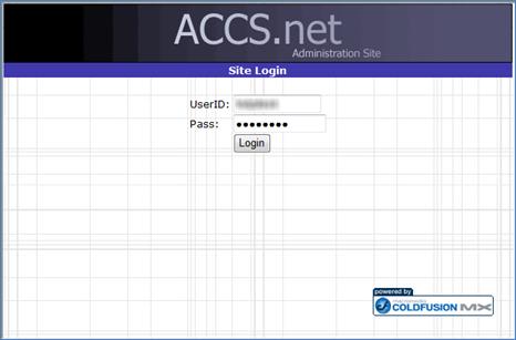
Figure 1 ACCS.net Administration Site Login Page
3. To access the user information database, move the mouse cursor over the “Internet Tools” drop-down menu and select the “User Management” link (Figure 2).
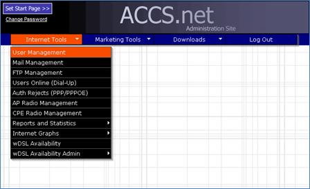
Figure 2 ACCS.net Administration Site Menu Page
4. The “User Management” page will load with a populated list of users.
5. Locate the user account of the malfunctioning radio by typing in the full entered name, last name, or username of the created user in the “Search:” textbox below the “Add New User” link on the “User Management” page (Figure 3). Click the button labeled “Search.”
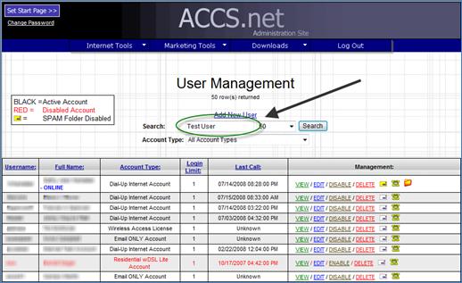
Figure 3 ACCS.net Administration Site User Management Page – Search
6. Once the search is complete, access the user account information by clicking on the “View” link to the right of the username under the “Management:” table heading.
7. The “User Management – View User” page will open in a new window. The radio and CCU information related to the account will be displayed on the right side of the page.
8. Open a Command Prompt window.
9. Test the connection to the customer’s WaveRider radio from the desktop computer by “pinging” the IP address of the radio.
a. At the command prompt, type “ping __._._.__ -l 1400 -n 30” where “__._._.__” is the “Radio IP” number listed in the “View User” window of the ACCS.net Administration Site. Press the “Enter” button.
i. -l 1400: Increases the size of data packet being sent to the network device at the listed IP address to 1400 bytes (default is 32 bytes).
ii. -n 30: Increases the number of pings sent to the network device at the listed IP address to 30 times (default is 4 times).
b. The ping program will attempt to send information to the radio a specified number of times, reporting the number of successful attempts, the time for each “data packet” to be sent to the radio and returned to the computer, and the percentage of lost data packets (Figure 4).
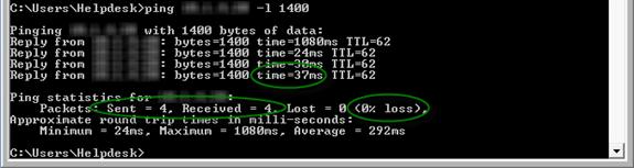
Figure 4 Command Prompt – Computer to WaveRider Radio Ping
10. Test the connection to the CCU from the customer’s WaveRider radio by “pinging” the IP address of the CCU from the WaveRider radio.
a. Start a Telnet session with the customer’s radio in the command prompt by typing “telnet __._._.__” where “__._._.__” is the “Radio IP” listed in the “View User” window of the ACCS.net Administration Site. Press the “Enter” button.
b. The Command Prompt window will request a password. Type the password listed as the “Radio Pass” in the “View User” window of the ACCS.net Administration Site. Press the “Enter” button.
c. A command line will display in the Command Prompt window that is the same as the “Radio Serial” listing in the “View User” page of the ACCS.net Administrative Site.
d. Type “ping __._._.__ 1400” where “__._._.__” is the “CCU Address (Radio)” listing in the “View User” window of the ACCS.net Administration Site. Press the “Enter” button.
e. The ping application will run until a keyboard button is pressed. Run approximately 70 to 100 pings.
i. icmp_seq: This field counts the number of consecutive, successful pings.
ii. Time: This field lists the time required (in milliseconds) for the data packet to be returned to the radio after it has been sent.
f. The ping application will provide a summary of the test results including the percentage of packet loss and the average “round-trip” ping time (Figure 5).
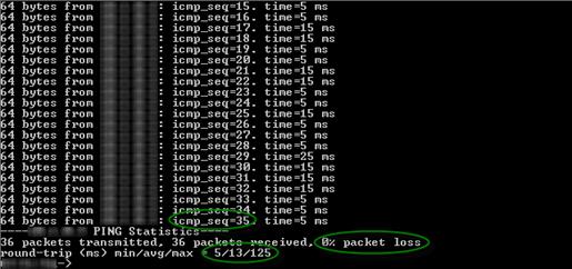
Figure 5 Command Prompt – Telnet WaveRider Radio to CCU Ping
11. Test the signal strength from the CCU to the WaveRider radio by using the RSSI application. In the telnet session, type the command ra rssi at the command prompt, and press the “Enter” key.
12. Eleven columns of data will continually update while the application is running (Figure 6).
a. RSSI [dBm]: Indicates the signal power level the radio is receiving from the CCU; the power level improves the less negative the number is.
b. R1: Indicates that 1 packet transmission retry had to be attempted.
c. R2: Indicates that a second packet transmission retry had to be attempted.
d. R3: Indicates that a third packet transmission retry had to be attempted.
e. F: Indicates that the packet transmission failed.
f. Retry%: Indicates what percent of packet transmissions had to be resent; the percentage should remain close to or at 0.
g. SQ: Indicates signal quality; the value should be as low as possible.
h. RNA, RNB: Indicates the connection quality to antenna A and antenna B, respectively; the value should be in the mid-20s or higher for at least one of the antennas, depending on the quality of the initial radio install at the customer’s location.
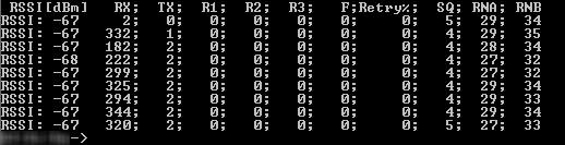
Figure 6 Command Prompt – Telnet WaveRider Radio to CCU RSSI Test
13. Press the “Enter” key to stop the RSSI test.
14. At the command prompt, type exit to exit the Telnet session, but leave the “Command Prompt” window open.
15. Test the connection to the customer’s WaveRider radio from the CCU by “pinging” the IP address of the radio from the CCU.
a. Start a Telnet session with the CCU in the Command Prompt window by typing “telnet __._._.__” where “__._._.__” is the “CCU Address (Radio)” listed in the “View User” window of the ACCS.net Administration Site. Press the “Enter” button.
b. The Command Prompt window will open a prompt for a password to be entered. Enter the appropriate password for the CCU, and press “Enter.”
c. A command line will display in the Command Prompt window that is the same as the “Radio Serial” listing in the “View User” page of the ACCS.net Administrative Site.
d. Type “ping __._._.__ 1400” where “__._._.__” is the “CCU Address (Radio)” listing in the “View User” window of the ACCS.net Administration Site. Press the “Enter” button.
e. The ping application will run until a keyboard button is pressed. Run approximately 70 to 100 pings.
i. icmp_seq: This field counts the number of consecutive, successful pings.
ii. Time: This field lists the time required (in milliseconds) for the data packet to be returned to the radio after it has been sent.
f. The ping application will provide a summary of the test results including the percentage of packet loss and the average “round-trip” ping time (Figure 5).
16. Compare the connection quality of all the radios communicating with the specific CCU by using the Air application (Figure 7).
a. In the telnet session at the command prompt, type air and press “Enter.”
b. All of the radios communicating to the CCU will appear in the window.
i. REGISTERED EUM ID: MAC address of the radio as indicated in the “Radio Serial” field of the “View User” page of the ACCS.net Administration Site.
ii. EUMs GOS/PRI: Level of subscribed service for each customer.
iii. RSSI dBm: Signal power level the CCU is receiving from each WaveRider radio.
iv. SQ: Indicates signal quality; the value should be as low as possible.
v. RNA dB: Indicates the connection quality to the CCU antenna; the value should be in the mid-20s or higher, depending on the quality of the initial radio install at the customer’s location.
c. The Air application also indicates the number of radios communicating with the CCU (Figure 7).
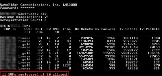
Figure 7 Command Prompt – Telnet CCU Air Test
17. Examine the data transfer rate of the radio and the core router using WinBox. Double click the WinBox shortcut on the computer desktop to open the program. The “WinBox Loader” pop-up window will open.
18. Type the IP address of the core router in the “Connect To:” textbox, and type the server username in the “Login:” textbox (Figure 8). Click the “Connect” button to connect to the server.
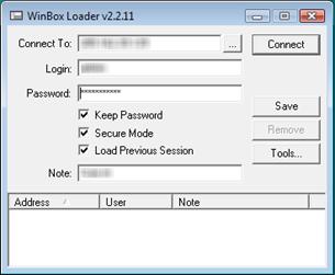
Figure 8 WinBox – Loader Pop-up Window
19. WinBox should open with the “Interface List” window already open. If it does not, click the button, labeled “Interfaces,” which is the first of a series of buttons on the left side of the window.
20. The “Interface List” window lists all of the user accounts connected via PPPoE, listed in the form <pppoe-______>, where “______” is the customer account username.
21. Scroll to the bottom of the page to the “Waverider” Ethernet listing. Every listing below the Waverider line is a WaveRider radio (Figure 9).
a. Tx Rate: The transmit speed of the core router to the radio; the customer’s download speed.
b. Rx Rate: The receive speed of the core router from the radio; the customer’s upload speed.
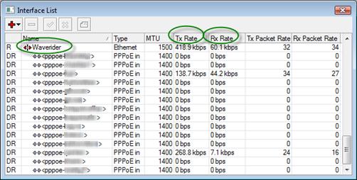
Figure 9 WinBox – Interface List Window
22. If the customer’s radio is not listed in the “Interface List” window, the customer’s radio has not been connected to the PPPoE server and, therefore, will not have Internet service.